Compact, accessible aluminum plates and blocks with clearly defined mounting interfaces are sensible first candidates for custom RC aluminum parts on a desktop CNC. A small outline alone does not make a part machinable: cutter access, holding and clearance, internal corners, wall support, and the part’s intended service all matter.
A shallow mounting adapter, an open pocketed electronics support block, and a deep multi-face housing can have similar outside dimensions yet require very different decisions. The first two can often be planned around accessible features and straightforward holding; the third may need a different orientation, additional setups, another process, or engineering validation before it becomes a practical first project.
Start With the Mating Interface
Before refining an RC part’s cosmetic outline, define the interfaces that make it functional: the bolt pattern that attaches it to the chassis, the surfaces that locate a servo or electronics module, and the clearance required for wires, rotating parts, suspension travel, and assembly tools. Those relationships determine whether the part can be installed and whether the RC assembly will work as intended.
A mounting adapter is a useful first concept because its job is explicit. It may connect one component to another through a known bolt pattern, provide a flat locating surface, and leave an open area for the mating hardware. The design question is not simply whether the plate fits within the machine’s work area; it is whether every hole, pocket, edge, and mating surface can be reached with the intended tool and held securely during machining.
The ED1 enclosed desktop CNC router is designed for prototypes, custom parts, and small-batch projects, and its published specifications include a 600W variable-frequency spindle, 300 × 200 × 120 mm work area, five-tool magazine, and aluminum capability. An automatic tool changer handles tools; it does not give a cutter access to a hidden cavity. Those platform facts describe the machine; they do not certify that a particular RC design will fit, perform under load, or meet a finished tolerance requirement.
A Shallow Adapter Plate Offers Accessible Features
Hypothetical example: imagine a shallow aluminum adapter plate that mounts a small electronics module to an RC chassis. It has a rectangular outline, a few through-holes matching the chassis bolt pattern, a recessed pocket that clears a connector, and rounded internal corners where the pocket meets the walls.
This design is a sensible candidate because its important features are accessible from one primary orientation. The mounting holes and pocket can be planned around a defined tool path, the plate can be supported on a flat bed, and the perimeter does not necessarily need to be cut free in the same operation. The shallow pocket also leaves room for cutter access rather than forcing a long tool deep into restricted walls.
Rotating end mills leave internal radii, so the pocket’s inside corners should be designed as radiused corners rather than assumed to be square. Designing the corner radius around the intended cutter is part of making the adapter practical, not a cosmetic afterthought.

An Open Support Block Adds Holding and Access Questions
Hypothetical example: consider an open pocketed electronics support block for an RC car. It has a broader base, a shallow open cavity for a receiver or speed controller, mounting holes through the base, and side walls low enough to leave the cavity accessible.
This can still be a good desktop-CNC candidate, but it introduces two additional questions: how the block will be held, and whether the cutter can reach every intended surface without contacting the fixture. A compact block with suitable side surfaces may suit a vise, while a thin or full-profile plate may be better supported on a flat bed.
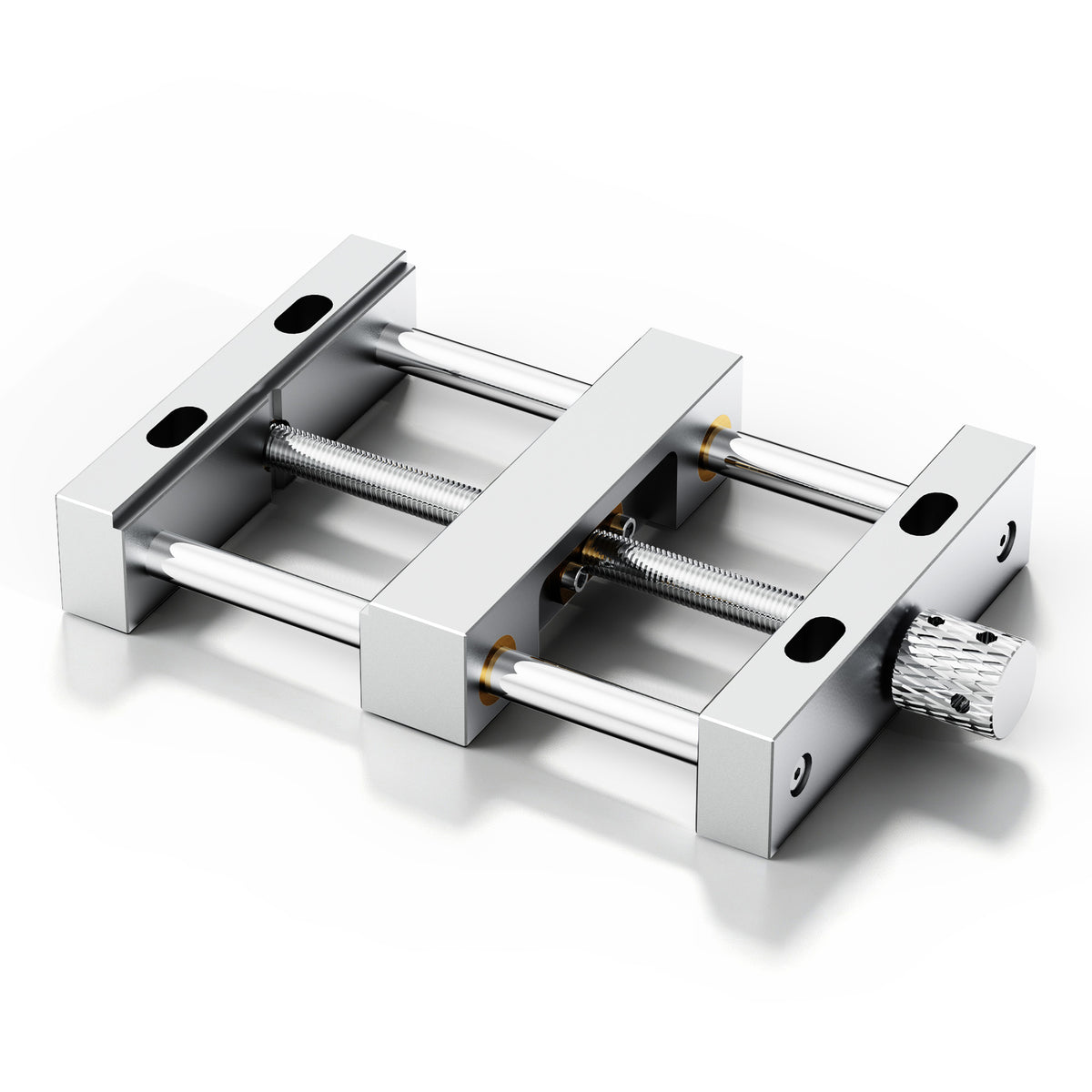
The ED1 aluminum vise bench clamp is a dedicated ED1 option for suitable side-gripped compact blanks. It addresses holding, but it does not solve cutter access by itself: the jaws, stock, tool holder, and cutter path must all leave the intended features reachable. If the block’s perimeter must be profiled completely free, plan how it will remain supported until the final release operation. Follow the machine’s stop and isolation procedure before releasing or repositioning stock; do not reach into the cutting area while it is moving.
Open pockets are generally more accessible than enclosed cavities because the cutter can enter from above. But depth, wall height, and corner radius still matter. Deep, narrow pockets and features beside tall walls can create cutter or workpiece vibration, deflection, and reduced accuracy or surface finish; restricted access and deep features can also leave material unmachined.
A Deep Multi-Face Housing Is a Different Project
Hypothetical example: now consider a compact aluminum housing for a small RC assembly, with mounting bosses on one face, a recessed lid interface on another, internal compartments, and a narrow opening for wiring. Its outside dimensions may be smaller than the adapter plate, yet it can be substantially harder to machine.
The difficulty comes from access and orientation, not size alone. Internal compartments may require a long tool to reach past walls; some faces may require the part to be turned; and internal corners may leave material behind if the intended tool cannot reach them. Deep holes, internal galleries, undercuts, restricted tool access, and parts requiring multiple setups can push against CNC process limits or leave material unformed.
A deep multi-face housing may still be achievable, but it is a more demanding first design. It may require redesigning the cavity as an open pocket, splitting the housing into simpler mating pieces, changing the orientation strategy, or using a process better suited to the internal geometry. The right response is not to abandon aluminum; it is to match the design to a process and setup that can actually reach every functional feature.
Outline Size Is Not the Machining Envelope
The ED1’s 300 × 200 × 120 mm work area is a nominal machine specification, not a guarantee that a part of those dimensions can be held, fixtured, and cut with full clearance. The usable envelope depends on the stock, fixture, vise or clamping arrangement, tool length, holder, spindle clearance, and the complete path the tool must travel.
For an RC part, a 100 mm-long plate may be easy to position on a flat bed but difficult in a vise if its perimeter must be cut free; a compact block may fit a vise well but become inaccessible if its cavity is too deep for the intended tool. This is why the first design should be chosen around its assembly interface and access path, not its largest outside dimension. A part that looks small in CAD can still require an unreachable internal feature, while a larger but open plate can be straightforward to machine.
Thin Features and Unsupported Geometry Need Attention
Thin walls, tall unsupported bosses, and narrow ribs can complicate an RC aluminum part even when they are visually simple. Cutting forces can deflect a thin wall or slender feature, and the part may flex or warp after machining if it lacks adequate stiffness.
For an RC adapter or support block, that often means favoring a more substantial base, adding a supportive web or boss where the design allows, and avoiding long slender features whose only purpose is appearance. The same reasoning applies to the part’s service: an identified aluminum alloy and temper, wall thickness, fastening method, and intended load all matter. “Aluminum” alone does not establish that a bracket, suspension arm, or drivetrain component will withstand a particular RC application; machine marketing does not certify a vehicle part’s load performance.
Choose the First Design Deliberately
Start with a shallow, accessible RC aluminum mounting adapter or an open support block whose bolt pattern, locating surfaces, and component clearances are already defined. Keep internal corners radiused, avoid deep restricted cavities and tall unsupported features where possible, and plan holding and cutter access alongside the part outline.
If the concept requires a deep multi-face housing, hidden internal features, thin unsupported walls, or geometry the cutter cannot reach, redesign it into a simpler accessible form, split it into mating pieces, change its orientation strategy, or consider another manufacturing process. For a separate validation step after the design is chosen, an aluminum cutting coupon can help produce a clear go-or-stop decision before committing a finished RC part; see A desktop CNC aluminum coupon that produces a clear go-or-stop decision.