CNC vise parallels raise and support a workpiece inside a suitable vise arrangement. The jaws still provide the side clamping. Choosing a taller support can expose more stock above the jaws, but it can also leave less stock between them. The useful height is the one that serves the intended cut while preserving an appropriate holding arrangement—not simply the height that makes the most material visible.
That tradeoff explains why a blank can look easier to machine after it is raised without actually becoming a better setup. Above-jaw exposure, underside support and side grip are different relationships. Each needs to make sense for the blank and operation.
What Parallels Support—and What the Jaws Hold
Haas Tooling describes parallels as supports for workpieces clamped in a vise or to a machine table. In a suitable vise setup, they establish the elevation of the blank's underside. They do not replace the jaws' contact with its sides. A support can put the top face in a convenient position while the side contact remains unsuitable for the planned machining.
Think of a rectangular blank that needs a pocket in its upper face. The underside needs an appropriate bearing arrangement, the sides need adequate retention, and the tool needs access to the pocket. Answering only the first question—where the underside sits—does not answer the other two. Nor does the word “parallel” establish the tolerance of the completed pocket.
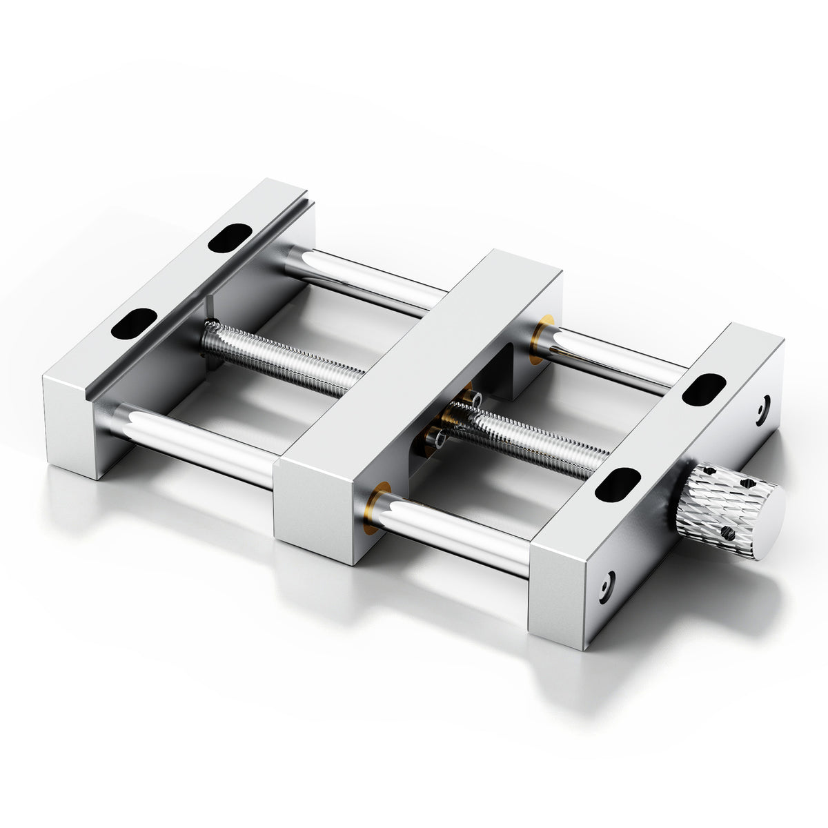
If you are planning this kind of work on an ED1, the TwoTrees ED1 aluminum vise bench clamp is the dedicated vise to consider for the holding arrangement. Decide how the actual blank will be held before selecting any additional support. A general milling parallel set should not be assumed to fit a particular vise merely because both are sold for CNC work.
Raising the Blank Trades Exposure for Potential Jaw Engagement
UNSW's stock-fixturing guidance identifies the basic height problem: stock positioned too low can bring the end mill into the jaws, while stock positioned too high may be insufficiently gripped. It is not a contest between a universally good low position and a universally good high position. The operation determines what must be exposed, and the holding arrangement determines what can be retained.
A hypothetical geometry makes the tradeoff easier to see. Imagine a flat-bottomed rectangular blank with straight vertical sides and straight jaw contact faces. Measure every height from the same reference plane. Let the jaw tops be at 25 mm, the top of the support at 10 mm, and the blank thickness be 18 mm. These are invented dimensions for explanation, not ED1 dimensions or a recommended setup.
The top of the blank is then at 10 + 18 = 28 mm. It stands 3 mm above the jaws. Between the support elevation and the jaw top is a potential vertical engagement of 25 − 10 = 15 mm. That figure describes overlap in this simplified geometry; it does not measure actual contact area or demonstrate sufficient holding force.
Now raise the support to 16 mm without changing the blank or jaws. The top becomes 16 + 18 = 34 mm, exposing 9 mm above the jaws. The potential vertical engagement becomes 25 − 16 = 9 mm. Raising the blank by 6 mm has gained 6 mm of exposure and lost 6 mm of potential jaw engagement. The extra access has come from a changed contact relationship, not from additional holding capacity.
Neither position is being declared safe or suitable. A real vise may have reliefs, steps or other contact geometry that this idealized example does not represent. A real blank may not contact the jaw over its entire apparent overlap. The calculation explains why height matters; the actual vise, blank, permitted support arrangement and operation determine whether a particular setup is acceptable.
Keeping a common reference is essential to that explanation. A parallel's advertised height is a component dimension. What matters to the setup is the resulting position of the supported blank relative to the jaws. Do not mix a height measured from the machine table with another measured from a different bearing surface and treat the subtraction as meaningful.
Choose Clearance for the Cut, Not Just the Uncut Top
A raised top face may be accessible at the start while the planned operation later enters the height occupied by a jaw. Return to the hypothetical lower position, with the top at 28 mm and the jaw top at 25 mm. If a facing operation removes 2 mm across the top, the new surface would be at 26 mm. Removing 4 mm instead would place it at 24 mm, below the jaw-top plane. This is geometry, not a recommendation to attempt either cut.
Crossing that plane does not mean every possible toolpath must hit a jaw; horizontal location matters too. It does mean that the original 3 mm of exposure cannot be carried unchanged into the clearance decision. A broad facing path passing over a jaw region and a small pocket contained inside the blank's upper face present different spatial questions. The required access belongs to the complete planned path, not merely to the starting surface.
A side contour adds another distinction. Raising the blank may expose a band of its side, but it does not make the portion occupied by the jaws available for machining. If the design requires a contour to continue through that held region, a taller support alone does not resolve the conflict between the feature and the grip. The operation or holding arrangement needs reconsideration.
The cutter tip is also only part of the moving assembly. The rest of the cutter and holder need appropriate clearance along the intended motion. Conversely, a support beneath the blank can occupy space needed by a through feature or another part of the operation. Raising stock changes its relationship to the jaws; it does not independently establish clearance everywhere else.
For an ED1 desktop CNC router, consider the vise, stock, intended supports and tooling as one arrangement within the machine. Nominal Z travel is not a ready-made allowance for that assembled setup. The relevant question is whether the required operation can be reached in the actual configuration while retaining the work appropriately.

When a Different Support Height Is Not the Answer
The rectangular example assumes a bottom that can bear on the intended supports. A previously pocketed underside changes that assumption. If the proposed supports meet a cavity rather than the intended bearing surface, choosing a more attractive top height has not solved the support problem. An irregular or flexible blank likewise needs an arrangement suited to its actual geometry, not a rectangular-block calculation applied by habit.
This is why selecting parallels is more than finding a bar that reaches the desired height. The supports must suit the vise's intended bearing arrangement and the blank, without conflicting with the operation. Their presence is not permission to improvise stacks or substitute an unsuitable support. Follow the procedures for the installed equipment rather than inferring approved contact surfaces from a product photograph.
There may be no useful compromise in the current arrangement. If lowering the stock obstructs the required cut and raising it leaves unsuitable retention, the solution is not automatically a still taller support or greater tightening force. Changing how the operation is divided or how the blank is held may be necessary. That decision follows from the feature being machined and the available holding geometry, not from a universal minimum engagement figure.
Make hands-on setup changes with the spindle stopped and follow the machine and vise procedures, including prescribed safe isolation. Secure the work and retain the required protective systems. Do not probe the limit by deliberately cutting close to a jaw, reach toward a moving tool, or remove supports while machining is in progress.
A useful support height leaves a coherent arrangement: the underside bears where intended, the jaws retain suitable stock, and the planned operation has the access it requires as material is removed. If raising the blank improves one relationship but defeats another, revise the arrangement before cutting.