A self-centering chuck moves its jaws together; an independent chuck lets each jaw be positioned separately. Jaw count does not settle that distinction. Four-jaw chucks exist in both forms, so choosing between a “three-jaw” and a “four-jaw” chuck without identifying the mechanism can lead to the wrong workholding decision.
For rotary CNC work, separate three questions: how many jaws contact the blank, how those jaws move, and which feature needs to line up with the rotation axis. A chuck can grip an outside surface without establishing that a bore or another existing feature shares that surface's axis. The required relationship matters more than a general claim that one chuck type is better.
Two Different Mechanisms Can Both Have Four Jaws
In a conventional self-centering scroll chuck, a common mechanism coordinates the jaws instead of requiring a separate adjustment for each one. Sherline describes this linked movement for its three-jaw scroll chucks and also offers four-jaw self-centering chucks. Its independent four-jaw chucks require the jaws to be set individually. These are distinct arrangements, not interchangeable names for the same four-jaw product.
Chandox's three-jaw versus four-jaw comparison explicitly discusses self-centering versions of both. That is a useful counterexample to the familiar shorthand “three jaws means self-centering, four jaws means independent.” Before applying advice from a comparison, establish which versions it actually compares.
The practical difference is the adjustment available to the setup. Linked movement coordinates the contacts through a shared mechanism. Independent movement allows different jaw positions, but those positions must be established appropriately. More adjustment freedom is not the same as automatic alignment.
| Documented arrangement | Jaw movement | What the label does not establish |
|---|---|---|
| Three-jaw scroll chuck | Jaws move together through a shared mechanism | That every existing feature shares the gripping surface's axis |
| Four-jaw self-centering chuck | Jaws move together rather than being positioned individually | That four contacts will suit any non-round blank |
| Four-jaw independent chuck | Each jaw is positioned separately | That the selected reference has already been aligned |
The table compares the documented mechanisms, not all products with those jaw counts. Actual jaw geometry, adjustment range, supported stock and mounting remain product-specific. It also does not rank holding force or finished-part accuracy; those results need evidence for the actual assembly and conditions.
Equal Jaw Travel Does Not Fit Every Shape
Consider a hypothetical round blank whose outside surface is the relevant reference. An appropriate linked-jaw chuck can bring its contacts toward that surface together, avoiding individual positioning of every jaw. That is the convenience the mechanism supplies. It does not inspect the blank's roundness or establish the position of features that the jaws never reference.
A non-round blank changes the contact problem. Imagine an ideal rectangle, centered on a proposed rotation axis, with its faces aligned to two opposing jaw pairs. Give it a hypothetical width of 40 mm and height of 20 mm. Its left and right faces are 20 mm from the center, while its upper and lower faces are 10 mm away. Those are illustrative dimensions, not an ED1 blank recommendation or a chuck capacity.
With identical contact faces constrained to equal radial positions, the two pairs cannot simultaneously occupy both required distances. As they close inward from outside the rectangle, the pair facing the wider dimension encounters the stock first; the other pair would still need to move farther inward. Four jaws do not remove that difference. Simply tightening a linked arrangement harder is not a solution to incompatible contact geometry.
A square is a different idealized case because its opposite faces can sit at equal distances from the center. Real stock still needs suitable shape and contact. Sherline qualifies its four-jaw self-centering description by requiring sufficiently accurate round or square material for all four jaws to grip properly. That condition is more useful than the sweeping claim that a four-jaw chuck holds anything.
Independent jaw positioning can accommodate unequal contact positions in a suitable arrangement. It does not make every irregular blank safe to machine. The actual contacts must retain the part securely without unsupported loading or interference. A mechanism that allows adjustment and an approved workholding setup that uses it successfully are different things.
Ask What Needs to Be Centered
Now change the hypothetical round blank: it already contains a bore, and the bore's relationship to the outside is unknown. The new operation must align with that bore rather than merely look centered on the outside. Closing jaws around the outer surface does not resolve the missing relationship. Even a perfectly centered outside would not prove that the bore shares its axis.
This is not an argument against self-centering workholding. If the outside is the correct design reference and its condition suits the documented hold, locating from it may serve the job. If an existing bore or another feature controls the design, the setup must establish that feature's relationship to the machine instead. “Centered” needs an object: centered on which surface or feature?
Independently adjustable jaws can provide a way to change the part's position rather than accepting the relationship established by linked contacts. The adjustment must still be guided and verified by an appropriate method. Sherline discusses indicator-based centering in its independent-chuck explanation; that is a description of its own equipment, not a setup procedure for an ED1 module or permission to run deliberately offset stock.
It is also possible to choose the wrong reference very consistently. Repeatedly gripping the same outside surface does not prove the location of a different feature, and switching to independent jaws does not identify that feature automatically. The design requirement should determine what relationship needs to be established before a mechanism is selected to help establish it.
Consequently, neither a self-centering label nor independent adjustment is a universal accuracy guarantee. A meaningful comparison concerns the actual requirement, a supported setup and evidence of the result. Jaw count by itself supplies none of those.
Apply the Distinction to a Dedicated Rotary CNC Assembly
A rotary CNC module is more than a chuck mounted in isolation. Its holding components, supports, machine mounting and programmed movement form one setup. The blank needs to remain secure while the cutter and holder can reach the intended features. Choosing a familiar chuck mechanism does not independently establish that the whole assembly fits the machine or the job.
When a project genuinely needs programmed circumferential or multi-sided access, the ED1 fourth-axis CNC rotary module kit is the dedicated accessory to evaluate with the ED1 desktop CNC router. Its role is to present secured stock for rotary CNC work. It is not a reason to transfer another manufacturer's chuck specifications, jaw-adjustment procedures or mounting options to the ED1.
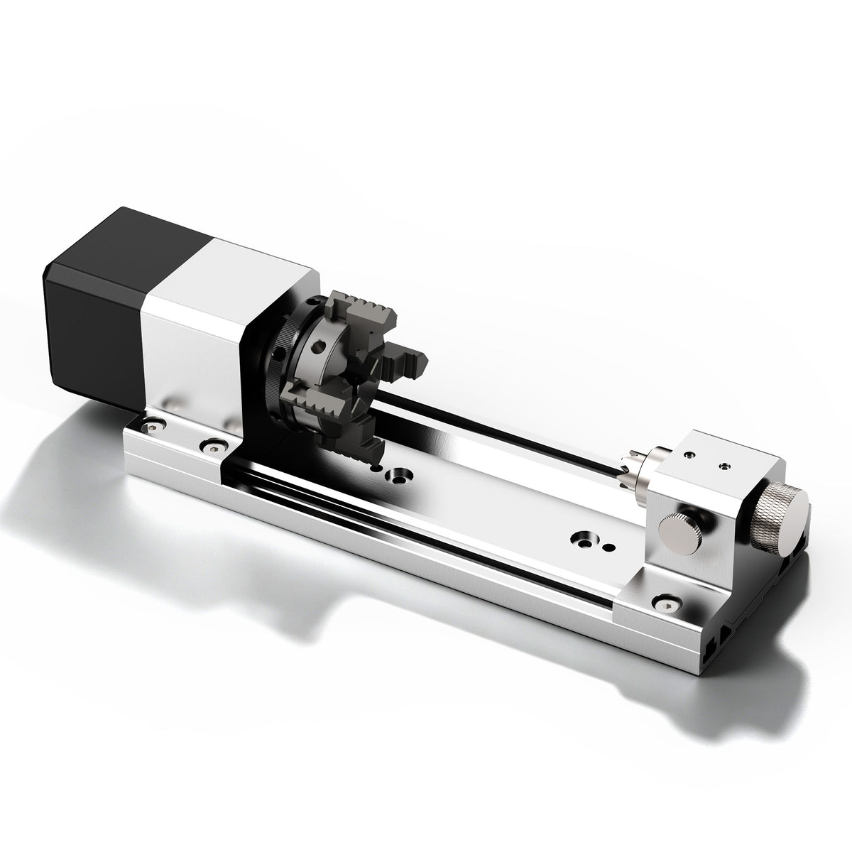
For an accessory supplied as a matched assembly, the first question is whether its documented holding arrangement serves the project—not which unrelated chuck could be substituted. A lathe chuck and a desktop rotary module may look familiar while having different mounting and operating requirements. Neither a matching jaw count nor a catalog diameter establishes interchangeability.
Physical capacity is another separate question. A dimensional drawing describes the accessory and its stated bounds; it does not show that every stock shape within a labeled diameter has suitable contact, support and cutter access. The dimensions help evaluate fit, while the holding method determines how the part is retained and related to the rotation axis.

Any hands-on setup must follow the exact machine and accessory procedures, with the spindle stopped and safe isolation used where prescribed. Secure the stock and remove adjustment tools before approved operation. General lathe advice is not an operating procedure for a CNC rotary accessory, and independent adjustment is not permission to improvise an eccentric setup.
Read the mechanism description first, then identify the gripping surface and the feature that actually controls the job. If the documented assembly can establish the required relationship while holding the part securely and leaving the work accessible, the choice has a practical basis. If it cannot, reconsider the approved holding method or blank preparation. Adding a jaw—or counting the jaws already present—does not supply a missing reference relationship.